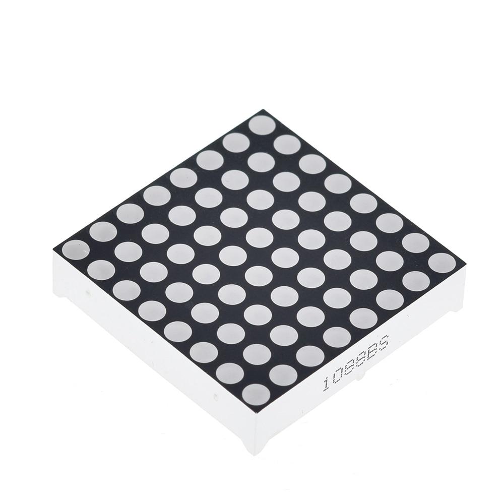
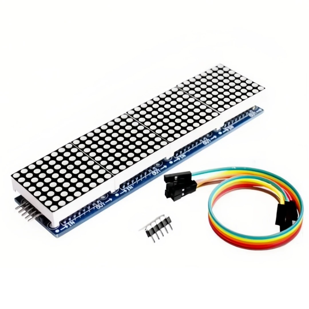
DescriptionLED displays are often packaged as matrixes of LEDs arranged in rows of common anodes and columns of common cathodes, or the reverse. Here’s a typical example, and its schematic:LED matrices are versatile displays that require both rows and columns connected to a microcontroller. Columns connect to LED cathodes (LOW for activation), and rows connect to LED anodes (HIGH for activation). To control a specific LED, set its column LOW and its row HIGH. For multiple LEDs in a row, set the row HIGH, then manage column states (LOW for ON, HIGH for OFF). You can create your own matrix with 64 LEDs, and pin assignment flexibility is available in the software. Circuit diagram of the LED matrix.SCHEMATICDIMENSIONPINOUTMatrix pin no.RowColumnArduino pin number15–1327–123–2114–31058–16 (analog pin 2)6–517 (analog pin 3)76–18 (analog pin 4)83–19 (analog pin 5)91–210–4311–64124–513–16142–715–78APPLICATIONThe LED matrix is mostly available in text signs.Most of the developers use it to design snake games.The clock of the matrix is also used by some companiesMost of the watches also have a matrix to make them look attractive and uniqueFEATURESThe LED matrix is operatable from any device at LOW voltage.Any text or image is drawable on the matrix.The matrix works on the forward bias with 1.5-2V only.The matrix is designable by simple LEDs and doesn’t have any special requirements.The programming may be found complex by some developers. So, there is a driver that helps to simplify the programming too.Scrolling, Blinking, or multiple kinds of patterns are performable on the matrix.DOCUMENTTutorialsSHIPPING LIST1 x 8×8 Dot Matrix Display